When we started SlewPro, the goal was simple: build a better way to serve small and mid-sized OEMs who were tired of being treated like an afterthought by the largest bearing manufacturers in the world. We were going to pick up the phone. Ship a 3D model with every quote. Design bearings around our customers' machines instead of forcing their machines to fit around someone else's catalog.
SlewPro Blog
What Got Us Here Won't Get Us There | Scaling SlewPro for the Next Chapter
Topics: slewing ring, slewing ring bearing
Hydraulic vs. Electric Slew Drives: A Practical Selection Guide for OEM Engineers
The choice between hydraulic and electric motorization for a slew drive is one of the most important decisions an OEM engineer makes during machine development. Both technologies are mature and capable. Neither is universally superior. The correct choice depends on application-specific factors such as load requirements, duty cycle, control precision, infrastructure, and total cost of ownership.
One critical but often overlooked factor is operating speed. Most slewing drives operate at very low rotational speeds—typically up to 5 RPM for smaller drives and approximately 2.5 RPM or lower for larger, high-moment units. This has important implications for how both hydraulic and electric systems are designed and evaluated.
Topics: slewing ring, slewing ring bearing
Slew Drives for Mobile Cranes and Utility Trucks: Engineering Reliable Rotation Under Load
A utility bucket truck extending 60 feet into the air to service power lines creates enormous tilting moments—forces trying to tip the entire vehicle over as the boom swings from side to side. A 40-ton mobile crane positioning steel beams on a construction site must rotate smoothly and precisely while resisting overturning forces that would flip an inadequately engineered machine. These critical mobile platforms depend on a single integrated component to enable safe, controlled rotation under extreme loads: the slewing drive system.
Topics: slewing ring, slewing ring bearing
How Material Pairings Affect Wear: A Guide for Long-Life Bearing Performance
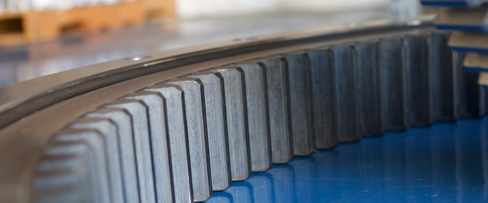
A construction crane's slewing bearing fails after just 5,000 operating hours—less than half its predicted service life. The investigation reveals nothing obviously wrong: loads remained within rated capacities, lubrication intervals were followed religiously, and operating conditions stayed within design parameters. Yet microscopic examination of the failed raceway shows severe wear patterns indicating material incompatibility between the hardened bearing races and the rolling elements. The root cause traces back to a seemingly minor specification decision made during design: selecting rolling element material based solely on availability rather than optimal pairing with the raceway steel grade and heat treatment.
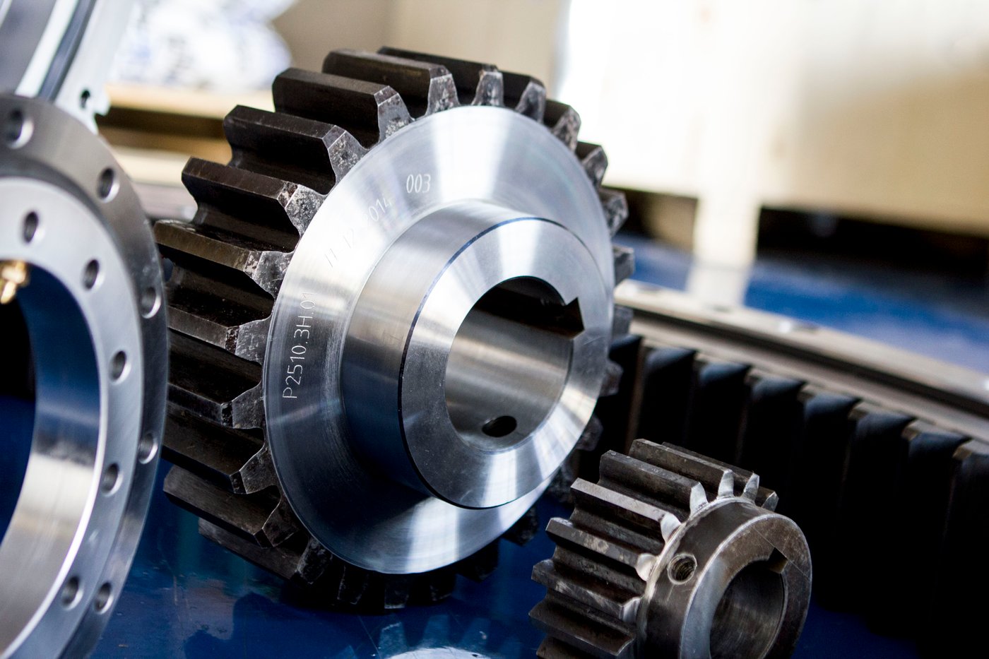
This scenario plays out repeatedly across industries wherever slewing bearings, slewing rings, and rotating machinery operate. The metallurgical marriage between contacting surfaces—raceway and rolling element, gear tooth and pinion, seal and housing—determines whether equipment achieves its designed service life or fails prematurely despite proper installation, adequate lubrication, and reasonable operating conditions. Getting material pairings right represents one of the most critical yet frequently underestimated decisions in bearing specification and design.
The science of material compatibility in rolling contact applications involves complex interactions between surface hardness, microstructure, residual stress states, and chemical composition. When materials are properly paired, wear progresses gradually at predictable rates, lubrication films remain stable, and service life reaches or exceeds design predictions. When materials are poorly matched, accelerated wear mechanisms activate: adhesive wear from chemical affinity between dissimilar materials, abrasive wear from hardness mismatches allowing debris generation, and fatigue wear from stress concentrations at material interfaces. Understanding these mechanisms and the material selection principles that prevent them enables engineers to specify bearing systems that deliver exceptional longevity and reliability.
Topics: slewing ring, slewing ring bearing
Why SlewPro Doesn’t Have a Catalog (And Why That’s Exactly the Point)
Read More
Rotary Motion Simplified: Integrating Slew Bearings, Slip Rings, and Rotary Unions for Automation Systems
Automation integrators are under constant pressure to deliver machines that are faster, more reliable, and easier to maintain. Whether you’re building robotic welding cells, rotary assembly stations, inspection systems, or palletizing equipment, one challenge shows up again and again: how to manage rotation while transferring power, signals, and fluids through the axis.
The ROI of Custom Machining: When Tight Tolerances Make All the Difference
Equipment manufacturers and engineers frequently face critical decisions about manufacturing precision when specifying slewing bearings, drives, and rings. Standard manufacturing tolerances—typically ±0.010" to ±0.020" for dimensional features—deliver adequate performance in many applications at minimal cost. However, precision machining with tight tolerances—often ±0.001" to ±0.005"—costs substantially more through additional machining operations, slower production rates, enhanced quality control, and specialized tooling requirements.
This cost differential creates tension between engineering ideals and budget realities. Finance teams question whether precision machining justifies its premium costs. Procurement departments pressure engineers to accept standard tolerances reducing component expenses. Project managers worried about schedules favor faster standard manufacturing over time-consuming precision processes.
Yet in high-speed rotation applications, heavy-load systems, precision positioning equipment, or installations where downtime costs are extreme, the seemingly abstract quality improvements from precision machining translate directly into quantifiable financial benefits. Smoother rotation reduces parasitic power losses saving energy costs throughout equipment life. Reduced vibration extends bearing life by 50-200% while protecting surrounding equipment from fatigue damage. Lower wear rates triple or quadruple service intervals slashing maintenance costs. Extended component life defers expensive capital replacement expenditures by years.
When these benefits are properly quantified and compared against precision machining premiums through rigorous return on investment analysis, the financial case for tight tolerances becomes compelling—particularly in applications where equipment operates continuously, downtime is expensive, energy costs are significant, or component replacement is difficult and costly.
This comprehensive financial and technical analysis examines how manufacturing precision affects slewing system performance across multiple dimensions, quantifies the operational and financial benefits of precision machining, identifies application characteristics where tight tolerances deliver maximum ROI, provides frameworks for cost-benefit analysis supporting specification decisions, and demonstrates through real-world examples how precision machining investments pay for themselves many times over through reduced lifecycle costs.
Topics: slewing ring, slewing ring bearing
Vertical vs. Horizontal Load Challenges: Engineering Slewing Rings for Directional Stress
Engineers specifying slewing rings for demanding applications often focus primarily on maximum load values—the peak axial, radial, and moment loads their equipment will experience. While these maximum values are certainly critical, an equally important yet frequently overlooked consideration is the direction and orientation of loads relative to the slewing ring's geometry and how those directional stresses fundamentally affect component design requirements.
A slewing ring supporting a vertical load—such as a crane superstructure pressing down on the bearing—experiences fundamentally different stress patterns, failure modes, and design requirements compared to a ring experiencing primarily horizontal loads—such as a vertical-axis wind turbine bearing supporting blade thrust forces. The same slewing ring that performs admirably under vertical loading may prove entirely inadequate when subjected to equivalent horizontal loads, and vice versa.
This directional sensitivity stems from basic mechanical principles governing how forces distribute through bearing components, how rolling elements and raceways interact under different load vectors, how gear teeth engage and transmit forces in various orientations, and how structural elements resist bending and deformation from directional stresses. Understanding these principles enables engineers to specify slewing rings optimized for their specific directional loading rather than accepting one-size-fits-all solutions that compromise performance, reliability, or cost-effectiveness.
The implications extend across the entire component specification. Material selection must account for which surfaces experience peak stresses from directional loads. Heat treatment specifications need to address the specific hardness requirements for load-bearing surfaces in different orientations. Gear geometry must be optimized for the tooth loading patterns created by directional forces. Manufacturing tolerances require prioritization based on which dimensional characteristics most critically affect performance under directional stress. Structural design must resist deformation in directions where loads create maximum bending moments.
This comprehensive engineering analysis examines how vertical and horizontal loads create different stress patterns and design challenges, the material and heat treatment implications of directional loading, gear design optimization for load direction, structural and tolerance considerations for directional stress resistance, and specification strategies ensuring slewing rings are properly engineered for their specific directional loading conditions rather than generically designed for average cases that may not reflect reality.
Topics: slewing ring, slewing ring bearing
Inside a Slew Drive Failure: Common Causes and How to Prevent Them
Slewing drive failures in critical equipment create cascading consequences that extend far beyond the failed component itself. When a crane's slewing system fails mid-operation, loads become uncontrollable safety hazards. When a solar tracker's drive ceases functioning, energy production stops and revenue disappears. When manufacturing automation equipment loses its rotational capability, production lines halt and delivery commitments are jeopardized.
The financial impact compounds quickly. Emergency repairs require premium labor rates and expedited parts shipping. Production downtime accumulates costs that can reach thousands or tens of thousands of dollars per hour. Equipment sitting idle represents unrecoverable opportunity costs. Customer relationships suffer when commitments can't be met. In severe cases, catastrophic failures create safety incidents with human injury risks and associated legal liability.
Yet the majority of slewing drive failures are preventable. They don't result from random component defects or unavoidable wear-out mechanisms. Rather, they stem from predictable, diagnosable root causes: installation errors that compromise proper operation from day one, operational conditions exceeding design parameters, contamination ingress degrading internal components, inadequate or improper lubrication accelerating wear, and design decisions that don't account for actual application demands.
Understanding these failure mechanisms—why they occur, how they progress, and what symptoms indicate developing problems—enables engineers to design systems that prevent failures rather than simply reacting when they occur. Equipment manufacturers can specify components properly and integrate them correctly. Operators can implement maintenance practices that preserve component integrity. Service organizations can identify and address emerging problems before they escalate to catastrophic failures.
This comprehensive diagnostic analysis examines the most common slewing drive failure modes in detail, exploring the mechanical and physical mechanisms causing each failure type, early warning signs that indicate developing problems, root cause analysis techniques identifying why failures occurred, and most importantly, engineering solutions and design practices that prevent failures from occurring in the first place.
Topics: slewing ring, slewing ring bearing
Custom vs. Standard Rotation Systems: When OEMs Should Choose Which Path
Equipment manufacturers face critical design pathway decisions early in product development that profoundly affect development timelines, manufacturing costs, equipment performance, and long-term competitiveness. Among the most consequential decisions: whether to design around standard, catalog rotation components or invest in custom-engineered solutions tailored specifically to equipment requirements.
This decision carries significant implications. Standard components promise immediate availability, predictable costs, and proven reliability. They enable rapid prototyping and minimize development risk. Custom components offer optimized performance, compact integration, and potential competitive differentiation—but at the cost of engineering investment, longer lead times, and development complexity.
The traditional framing presents this as a binary choice: standard or custom. Equipment engineers reluctantly accept compromises inherent in standard components, or they commit to fully custom solutions accepting the associated costs and timelines. This false dichotomy forces suboptimal decisions—either accepting performance limitations from standard parts or incurring unnecessary custom engineering expenses.
A more sophisticated approach recognizes that rotation systems comprise multiple elements—slewing bearings providing load support and rotational capability, hydraulic swivels transferring fluid across rotating interfaces, slip rings enabling electrical connections through rotation, and mounting provisions integrating components into equipment structures. These elements don't all require the same design approach. Strategic hybridization—combining standard components where they suffice with custom elements where they deliver disproportionate value—often provides optimal technical and economic outcomes.
The partnership between SlewPro and United Equipment Accessories enables precisely this hybrid approach. SlewPro's comprehensive range ofstandard slewing bearings and drives addresses most load-bearing and rotational requirements without custom engineering. UEA's expertise in custom hydraulic swivels and slip rings delivers application-specific motion transfer solutions. Together, they provide rotation systems that balance standardization benefits with custom optimization where it matters most.
This comprehensive guide examines when standard rotation components suffice and when custom engineering delivers value, how to evaluate the custom-versus-standard decision systematically, the hybrid approach combining standard bearings with custom motion-transfer elements, real-world applications demonstrating optimal pathway selection, and implementation strategies for equipment manufacturers navigating these design decisions.
Topics: slewing ring, slewing ring bearing
Subscribe Here!
Recent Posts
Case Study: SlewPro Partnership Saves Time & Money
When Wolf Robotics needed a quick turnaround on a new slewing bearing for a special project in 2017, SlewPro was the only company able to meet the time and specification requirements. The project met all requirements and was on budget, earning more trust from Wolf Robotics’ engineering team.


