A utility bucket truck extending 60 feet into the air to service power lines creates enormous tilting moments—forces trying to tip the entire vehicle over as the boom swings from side to side. A 40-ton mobile crane positioning steel beams on a construction site must rotate smoothly and precisely while resisting overturning forces that would flip an inadequately engineered machine. These critical mobile platforms depend on a single integrated component to enable safe, controlled rotation under extreme loads: the slewing drive system.
Unlike stationary cranes or industrial machinery operating in controlled environments, mobile cranes and utility trucks face unique engineering challenges. They must deliver heavy-duty performance from compact packages fitting within tight chassis constraints, operate reliably across temperature extremes from Arctic winters to desert summers, withstand constant vibration and shock loads during highway transport, resist contamination from road dust, rain, and construction site debris, and provide holding torque that, in many worm gear configurations, resists boom movement during power failures or hydraulic line breaks, though dedicated mechanical brakes are recommended for safety-critical applications.
Traditional bearing and gearing systems assembled from discrete components can struggle to meet these conflicting demands for compactness, strength, reliability, and safety in mobile equipment—though alternative designs do exist. The slewing drive integrates bearing, gearing, housing, and sealing into a single factory-assembled unit specifically engineered for the demanding mobile crane and utility truck environment. Understanding how these critical components enable safe, efficient operation—and how to specify them properly for commercial vehicle applications—separates successful equipment designs from costly field failures.
Understanding Mobile Crane and Utility Truck Demands
The Mobile Equipment Operating Environment
Mobile cranes and utility trucks operate under conditions that would quickly destroy equipment designed for stationary industrial service.
Road Transport Vibration subjects slewing drives to constant shock and vibration as vehicles travel between job sites. A utility truck driving 50 miles daily over rough urban streets, railroad crossings, and potholed highways experiences vibration and impact loads absent in stationary equipment. The slewing drive must maintain bearing preload, gear mesh alignment, and seal integrity despite this constant battering that loosens fasteners, damages seals, and causes wear in conventional assemblies.
Environmental Exposure proves far more severe than indoor industrial applications. Equipment operates in rain, snow, extreme heat, and freezing cold without environmental protection. Road salt in winter climates creates aggressive corrosion. Construction site dust infiltrates any inadequately sealed bearing. Temperature swings from -20°F overnight to 90°F midday create condensation inside bearings, promoting rust. Slewing drives for mobile equipment require robust sealing systems and corrosion-resistant materials surviving years of outdoor exposure.
Variable Loading Conditions challenge drive systems with forces that change constantly. A crane lifting a 10-ton load creates one set of forces; swinging that load 90 degrees generates completely different dynamic loads from acceleration and deceleration. Extending the boom changes the moment arm, multiplying tilting forces. Operating on sloped ground adds asymmetric loading. The slewing drive must handle worst-case combinations of axial loads (weight pressing down), radial loads (side forces), and tilting moments (forces trying to tip the upper structure) that occur simultaneously during normal operation.
Space and Weight Constraints limit mobile equipment designs in ways stationary machinery never encounters. Every pound added to a truck crane reduces payload capacity or requires chassis upgrades. Height restrictions determine maximum slewing drive profile to maintain vehicle clearances. Mounting points must align with chassis structure designed primarily for road transport, not crane loads. Achieving necessary strength within these constraints demands precision engineering that assembled component systems often cannot practically deliver.
Critical Performance Requirements
The unique demands of mobile cranes and utility trucks create specific performance requirements that drive slewing drive specification.
Moment Load Capacity determines whether the drive can resist tilting forces from extended booms and offset loads without bearing distortion or failure. A utility bucket truck with 60-foot boom reach and 1,000-pound platform load creates perhaps 60,000 ft-lbs of overturning moment when positioned horizontally. The slewing drive's large-diameter bearing distributes these forces over hundreds of square inches, maintaining alignment under loads that would overwhelm smaller bearings regardless of their rated capacity.
Self-Locking Safety prevents dangerous boom movement during power or hydraulic failures. Worm gear slewing drives can provide mechanical self-locking in many configurations—the high reduction ratio and geometry mean output loads cannot easily back-drive the input under static conditions. However, self-locking behavior is not guaranteed in all designs; it depends on gear geometry, friction conditions, and component wear. Vibration present in mobile equipment can in some circumstances overcome the self-locking effect. For this reason a dedicated mechanical brake is strongly recommended as a redundant holding device. This inherent safety feature proves invaluable when workers occupy aerial platforms or when crane loads hang suspended—conditions where unwanted movement creates life-threatening hazards.
Compact Package Size enables designs fitting within vehicle chassis constraints while delivering required performance. A precision slewing drive measuring 24 inches diameter might deliver 50,000 ft-lbs torque capacity—performance requiring conventional motor-gearbox-bearing assemblies measuring several feet across and weighing significantly more. This compactness proves essential when mounting points must align with chassis frame rails and overall height must maintain vehicle clearance requirements.
Smooth Low-Speed Operation ensures precise positioning and operator control. Boom slewing speeds typically range from 0.5 to 3 RPM—far slower than most industrial applications. At these low speeds, gear quality becomes critical. Any tooth spacing errors or profile inaccuracies create jerky motion and position uncertainty. Stick-slip behavior from inadequate lubrication causes the boom to jump rather than move smoothly. Precision manufacturing with tight tolerances ensures smooth, controllable rotation even at minimal speeds.
Slewing Drive Architecture for Mobile Applications
Integrated Bearing and Gearing Design
The slewing drive integrates multiple functions that would require separate components in traditional designs.
Large-Diameter Slewing Bearing forms the foundation, providing the load path for all forces while enabling smooth rotation. Unlike standard rolling element bearings designed primarily for radial or axial loads, slewing bearings excel at moment loads—tilting forces from offset masses. The large diameter creates substantially greater resistance to overturning moments compared to smaller bearings; increasing bearing diameter significantly improves moment capacity, though the precise relationship depends on bearing type, cross-section geometry, and rolling element configuration.
Single-row four-point contact ball bearings represent the most common configuration for truck cranes and medium-duty utility trucks. This design uses specially shaped raceways allowing each ball to contact both rings at four points, supporting axial loads in either direction, radial loads, and substantial moments within a compact cross-section. The design minimizes height—critical for chassis mounting—while delivering excellent moment capacity for given diameter.
Double-row ball bearings or crossed-roller designs provide even higher capacities for heavy-duty applications. These configurations use two rows of rolling elements or crossed cylindrical rollers achieving superior rigidity and load capacity at the expense of slightly larger envelope and higher cost. The selection depends on application loads, available mounting space, and budget constraints.
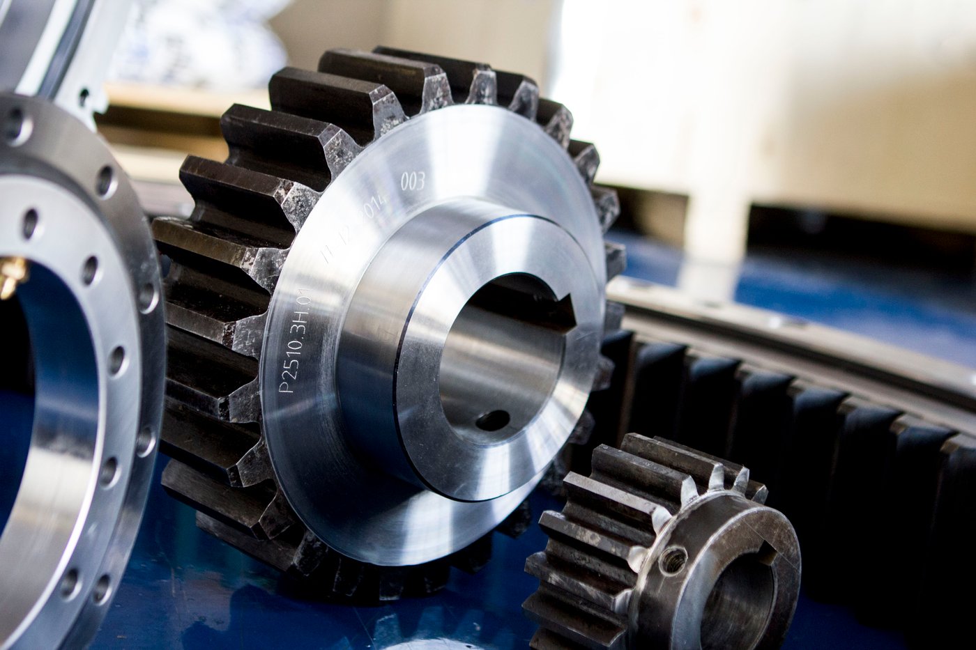
Integrated Gearing eliminates alignment concerns and simplifies installation compared to separate gearboxes. Most mobile crane slewing drives use worm gear reduction providing high ratios (often 50:1 to 100:1 or higher) in single-stage designs. The worm screw meshes directly with gear teeth cut into the slewing ring, creating a compact assembly with no separate gearbox housing or mounting requirements.
The worm gear configuration delivers critical advantages beyond compactness. Worm gears can provide self-locking in many configurations, though a dedicated brake should be specified for safety-critical applications involving personnel or suspended loads. The high reduction ratio means modest hydraulic motors produce enormous output torque. The sliding contact in worm gearing provides some damping of shock loads, protecting the drive from impact forces during boom swing starts and stops. While worm gears exhibit lower efficiency (typically 40-60%) than spur gears, the other benefits prove more valuable for mobile crane applications where duty cycles are modest and safety features take precedence.
Sealed Housing Construction protects internal components from environmental contamination while retaining lubricant. Mobile equipment faces constant exposure to rain, road spray, dust, and construction debris that would quickly destroy unsealed bearings. Multi-stage sealing systems use combinations of labyrinth seals, lip seals, and exclusion seals creating barriers against contamination while accommodating the thermal expansion and breathing that occurs with temperature cycling.
Grease lubrication remains the most widely used approach in mobile slewing drives, offering simplicity and compatibility with a broad range of bearing sizes and operating conditions. Larger drives sometimes use oil bath lubrication, where the oil level submerges critical components and continuously washes away particles that penetrate outer seals; however, this approach adds complexity and is less universally applied than grease systems. Desiccant breathers are used to filter and dry the air that enters the housing as temperatures cycle, helping to reduce moisture ingress—though they do not maintain positive internal pressure.
Mounting Interface Engineering
Proper integration between the slewing drive and vehicle chassis critically affects reliability and performance.
Bolt Circle Design must distribute loads uniformly while accommodating chassis structure. Large-diameter bolt circles (approaching the bearing diameter) minimize cantilever distances and bending moments in mounting structures. The bolt pattern must align with chassis frame rails or purpose-built turntable support structures capable of transferring loads to the vehicle frame without localized overstress or fatigue crack initiation.
Bolt size and spacing reflect the forces being transferred. Heavy-duty crane applications might use 24-40 mounting bolts in 1" to 1.5" diameters, while smaller utility trucks use 16-24 bolts in 3/4" to 1" sizes. The critical consideration: preventing bolt fatigue from cyclic loading. Mobile equipment experiences millions of load cycles over service life as booms extend, retract, swing, and support varying loads. Proper bolt preload and grade selection ensure adequate fatigue resistance.
Pilot Diameter Interfaces center the slewing drive precisely on mounting structures. A close-tolerance pilot diameter registers the drive concentrically, preventing eccentric mounting that would create uneven bearing loading and accelerated wear. The pilot must be long enough to maintain alignment despite thermal expansion and frame flexure but not so long that thermal expansion creates binding. Typical practice specifies 0.002-0.005" diametral clearance per foot of diameter, allowing thermal movement while maintaining adequate centering.
Mounting Face Flatness affects load distribution across bolted joints. An uneven mounting surface creates localized high stress at contact points rather than uniform compression across the joint. Specifications typically require 0.005-0.010" total indicator reading (TIR) flatness across mounting faces, ensuring that tightening bolts compress the joint uniformly without creating stress concentrations or leaving gaps that allow movement under load.
Application-Specific Requirements
Truck-Mounted Cranes
Truck-mounted cranes span a wide range from small service cranes (5-10 ton capacity) through medium-duty logistics cranes (15-30 tons) to heavy-duty construction cranes (40+ tons). Each category creates specific slewing drive demands.
Knuckle Boom Cranes feature articulated booms with multiple joints, common on delivery trucks, utility vehicles, and material handling equipment. These cranes typically operate at modest capacities (3-15 tons) with frequent cycling—dozens of lifts per day loading and unloading trucks. The slewing drive must provide smooth, controllable rotation under varying loads while surviving high cycle counts. Compact size proves essential as these cranes mount behind truck cabs on relatively small chassis.
The duty cycle drives specification decisions. A delivery truck crane might perform 50-100 slewing movements daily, accumulating 15,000-30,000 cycles annually. Over a 10-year service life, this totals 150,000-300,000 cycles—demanding robust bearing design, proper lubrication, and quality gearing to achieve service life targets without intermediate bearing replacement. SlewPro's application engineering helps customers analyze duty cycles and specify drives appropriately for actual operating conditions.
Telescopic Boom Cranes extend to greater heights and capacities, common on construction sites for placing steel, concrete panels, and mechanical equipment. Capacities range from 15 tons for smaller models to 60+ tons for heavy-duty construction cranes. The telescoping boom creates variable moments as it extends and retracts—maximum moment occurs at full extension with load at the tip.
Load chart calculations determine required slewing drive capacity. Consider a 40-ton crane with a 100-foot boom lifting 20 tons at maximum radius. The lifted load alone generates 4,000,000 ft-lbs of overturning moment about the slewing centerline. Adding boom self-weight (for example, a 15,000-lb boom with its center of gravity at 50 feet from center) contributes an additional 750,000 ft-lbs, bringing the gross overturning moment to approximately 4,750,000 ft-lbs before counterweight effects are applied—illustrating the enormous forces demanding large-diameter slewing bearings with substantial section thickness. The drive must also provide sufficient torque to accelerate this extended boom smoothly from rest while resisting the inertia trying to continue rotation when stopping. Dynamic forces from starting and stopping often exceed static load requirements.
All-Terrain and Rough-Terrain Cranes operate in demanding off-road conditions requiring enhanced durability. These mobile cranes work on construction sites with limited preparation, experiencing additional shock loads from operating on uneven ground. Slewing drives require robust construction tolerating impacts and vibration beyond highway operation. Enhanced sealing protects against mud, dust, and water encountered on construction sites. Wider operating temperature ranges accommodate equipment working from desert heat to Arctic cold.
Aerial Work Platforms and Bucket Trucks
Utility companies, telecommunications providers, tree services, and electrical contractors rely on aerial work platforms for elevated access. These applications create unique safety demands where slewing drive reliability directly protects worker lives.
Insulated Boom Designs for electrical utility work place additional constraints on slewing drive selection. The rotating bearing sits between the truck chassis (grounded) and the boom structure (potentially at high voltage during hot-stick work on energized lines). Designs must prevent electrical current paths through the slewing bearing that could energize the truck chassis or create shock hazards for workers. This typically requires insulating bushings, non-conductive mounting interfaces, or complete isolation of the slewing drive from boom-mounted components.
Dual-Control Systems allow operation from both ground controls and platform-mounted controls. This redundancy demands reliable slewing drive integration with control systems and smooth, predictable response to operator inputs from either location. Worm gear designs that provide self-locking under normal static conditions contribute to safe operation, though dedicated mechanical brakes remain the appropriate primary holding device for aerial platform applications.
Service Life and Reliability take priority over cost for utility fleet operators. Bucket trucks typically remain in service 15-20 years, operating daily in all weather conditions. Fleet managers spec slewing drives for maximum reliability and minimal maintenance, accepting higher initial costs to avoid the substantial expense and downtime of premature bearing replacement. Extended lubrication intervals (1,000+ hours) and sealed-for-life designs reduce maintenance requirements while ensuring reliability throughout vehicle service life.
Service Trucks and Specialized Equipment
Beyond traditional cranes and bucket trucks, numerous commercial vehicles rely on slewing drives for rotating booms, platforms, or equipment packages.
Mechanic Service Trucks use small service cranes (2-5 ton capacity) to load and unload tools, parts, and equipment. These cranes experience frequent use but modest loads, requiring compact slewing drives delivering adequate performance at minimum cost. Reliability remains important—a breakdown crane that itself breaks down creates embarrassing service calls—but the moderate duty cycle and lower safety criticality compared to manned aerial platforms justify less expensive drive configurations.
Drilling Rigs and Digger Derricks for utility pole installation and foundation drilling use slewing drives to position heavy equipment packages. A pole-setting truck might rotate a derrick boom, earth auger, and associated hydraulics totaling several thousand pounds. The equipment experiences intermittent heavy loading during drilling operations combined with frequent positioning movements between holes. Slewing drives must provide the torque for these heavy packages while maintaining positioning precision ensuring accurate hole placement.
Towing and Recovery Equipment increasingly incorporates rotating booms for vehicle recovery and cargo handling. Heavy-duty wreckers use rotating booms to access and lift disabled vehicles from ditches, embankments, and accident scenes. The slewing drive must deliver high torque for lifting while providing controlled rotation positioning the boom over varied terrain. The unpredictable loading and harsh operating conditions demand robust construction and generous safety factors.
Forestry Equipment including timber loaders, log trucks, and mobile processing equipment use slewing drives in demanding applications. Log handling creates substantial shock loads as multi-ton logs drop into bunks or are grasped by grapples. Operating environments in forest settings expose equipment to constant contamination from sawdust, tree sap, mud, and moisture. Enhanced sealing and corrosion protection prove essential for acceptable service life. The equipment often operates remotely with minimal maintenance infrastructure, demanding exceptional reliability.
Material Selection and Durability Engineering
Bearing Materials and Heat Treatment
The slewing bearing's raceways and rolling elements determine load capacity and service life, making material selection critical.
Bearing Steel Selection typically uses medium-carbon alloy steels like 42CrMo (similar to AISI 4140/4142) providing excellent hardenability, good core strength, and adequate toughness for mobile equipment shock loads. Unlike precision bearing applications using through-hardened 52100 bearing steel, mobile crane slewing bearings typically use case-hardened or induction-hardened construction creating hard, wear-resistant surfaces (55-60 HRC) over tough, ductile cores (30-40 HRC) resistant to impact damage.
This design philosophy recognizes the operational realities of mobile equipment. Shock loads from boom swings, road transport vibration, and occasional overloads create impact forces that could crack fully hardened components. The case-hardened design provides wear resistance where needed (at the raceway surface) while maintaining impact resistance in the core material. If momentary overloads create surface indentations, the tough core prevents crack propagation that could lead to catastrophic failure.
Induction Hardening creates ideal hardness patterns for slewing ring raceways. The process heats only the raceway surface and immediate subsurface material using electromagnetic induction, followed by water quenching creating a hardened case typically 0.060-0.120" (1.5-3mm) deep. The selective heating minimizes distortion compared to through-hardening or carburizing the entire ring, reducing manufacturing costs while achieving optimal properties.
Case depth specifications balance surface support against core strength. Insufficient case depth allows contact stresses to penetrate below the hardened layer into the softer core, causing subsurface-initiated fatigue failures. Excessive case depth wastes heat-treating time and increases distortion without performance benefits. For mobile crane applications with Hertzian contact stresses from ball or roller bearings, typical case depths of 0.080-0.100" (2.0-2.5mm) provide adequate support for surface hardness while maintaining impact resistance.
Gear Tooth Design and Hardening
The gear teeth transmitting torque through the slewing drive require optimization for mobile equipment operating conditions.
Tooth Hardening Approach significantly affects wear life and load capacity. Gear teeth can be hardened through the same induction process used for raceways, creating 55-60 HRC surface hardness over a tough core. This approach proves cost-effective and provides good wear resistance for typical mobile crane duty cycles. Alternatively, case carburizing followed by hardening creates higher surface hardness (58-62 HRC) with optimized carbon gradient for severe-duty applications experiencing high loads or extended service life requirements.
The hardening pattern should extend across the entire tooth working surface. Partial hardening leaving soft zones creates accelerated wear in unhardened areas. Modern induction hardening equipment using CNC-controlled scanning achieves uniform hardness across all teeth, ensuring consistent wear patterns and maximizing gear life. SlewPro's quality manufacturing includes comprehensive hardness testing verifying uniform properties meeting specifications.
Tooth Profile Accuracy determines smoothness and noise during operation. Mobile equipment operators and workers in aerial platforms are acutely aware of gear noise and vibration. Rough gear mesh creates objectionable noise, vibration transmitted through the boom, and accelerated wear from impact loading between meshing teeth. Precision gear cutting followed by hardening and finish grinding (when required for premium applications) produces quiet, smooth operation even under load.
Gear quality specifications balance performance and cost. Industrial quality gearing (AGMA Quality 8-9) proves adequate for many mobile crane applications, providing acceptable noise and wear life at reasonable cost. Premium applications requiring minimal vibration or extended service life justify higher quality levels (AGMA Quality 10-11) achieved through grinding after hardening, though manufacturing costs increase significantly.
Corrosion Protection Systems
Mobile equipment operates continuously in corrosive environments demanding comprehensive protection strategies.
Protective Coatings shield base materials from environmental attack. Zinc-rich primer provides galvanic protection—the zinc coating corrodes preferentially, protecting underlying steel even if the coating is damaged. This sacrificial protection proves particularly valuable in winter climates where road salt creates aggressive corrosion. Topcoats of epoxy or polyurethane paint create additional moisture barriers while providing color and UV resistance.
For severe corrosion environments—marine applications, extreme winter climates with heavy salt use, or equipment operating in chemical plants—enhanced coatings justify their cost premium. Thermal spray zinc or aluminum coatings provide thicker, more durable protection than conventional paint systems. Specialized epoxy systems formulated for marine environments resist salt water and humidity penetration. The coating investment proves modest compared to premature bearing replacement from corrosion damage.
Stainless Steel Components eliminate corrosion in the most demanding applications. Fasteners, seals, and occasionally entire bearing rings can be manufactured from corrosion-resistant stainless alloys. While stainless bearing steels (like 440C) exhibit somewhat lower load capacity than carbon steel equivalents, they eliminate corrosion as a failure mode—valuable for equipment that must operate reliably despite harsh environmental exposure. The cost premium limits widespread adoption, but critical applications justify the investment.
Sealing System Design represents perhaps the most important corrosion protection element. Keeping moisture and contaminants out proves more effective than trying to protect components after contamination occurs. Multi-stage sealing with primary seals handling bulk exclusion, secondary seals providing backup protection, and desiccant breathers filtering and drying incoming air to reduce moisture ingress creates robust protection enabling extended service life even in harsh environments.
Specification and Selection Best Practices
Load Analysis for Mobile Equipment
Proper slewing drive selection begins with comprehensive understanding of all loads the drive experiences during operation.
Static Load Calculations determine forces during worst-case positioning. For a truck crane, this typically occurs with maximum rated load at maximum boom extension and elevation producing peak overturning moment. The calculation must include the boom weight (concentrated at the boom center of gravity), counterweight forces, and lifted load, all creating moments about the slewing centerline.
A worked example: Consider a 30-ton truck crane with an 80-foot boom lifting 15 tons at maximum radius. The 15-ton (30,000-lb) load at 80 feet from the slewing centerline generates 2,400,000 ft-lbs of overturning moment. The boom itself (perhaps 8,000 lbs with its center of gravity located 40 feet from center) adds 320,000 ft-lbs. Counterweights reduce the net moment, but the gross overturning moment before counterweighting totals approximately 2,720,000 ft-lbs—illustrating the enormous forces requiring large-diameter slewing bearings with substantial cross-sections to resist overturning without distortion.
Dynamic Load Factors account for forces from acceleration and deceleration. Swinging the boom from rest to operating speed (perhaps 2 RPM) requires accelerating the entire rotating mass—boom, counterweights, lifted load, and upper structure. The angular acceleration creates inertial forces adding to static loads. Similarly, stopping rotation requires deceleration forces. Engineers typically apply dynamic factors of 1.25-1.5× static loads for mobile crane calculations, ensuring adequate capacity for normal operating dynamics.
Safety Factors provide margin against uncertainty, variable loading, and peak loads exceeding calculated values. Mobile equipment experiences unpredictable loading—sudden wind gusts on extended booms, load drops creating shock loads, operation on slopes creating asymmetric forces. Conservative engineering applies safety factors of 2.0-3.0 for mobile crane slewing drives, doubling or tripling calculated loads before selecting bearing size. This approach ensures reliable operation despite real-world conditions differing from idealized calculations.
Duty Cycle and Service Life Considerations
Understanding how equipment actually operates determines appropriate slewing drive specifications for achieving target service life.
Operating Hours Analysis establishes total expected service. A utility bucket truck might operate 8 hours daily, 250 days annually (2,000 hours/year). Over a 15-year vehicle life, this totals 30,000 operating hours. However, slewing operation represents only a fraction of operating time—perhaps 20% for a bucket truck (6,000 hours actual slewing). This actual slewing time determines bearing life calculations rather than total vehicle operating hours.
Cycle Counting quantifies repetitive motions affecting fatigue life. Each complete rotation of the boom from one side to the opposite constitutes one cycle. A bucket truck might perform 30-50 boom positioning movements daily. Over 15 years at 40 moves/day, 250 days/year, this accumulates 150,000 cycles. The slewing bearing must deliver this cycle count without fatigue failure, guiding bearing type selection and sizing decisions.
Load Spectrum Analysis recognizes that not all cycles occur at maximum load. A crane rated for 30 tons might lift maximum capacity occasionally but typically operates at 50-70% rated capacity. Creating a load spectrum showing percentage of cycles at various load levels enables more accurate life calculations than assuming all cycles occur at maximum rated load. This refined analysis often reveals that moderately larger bearing sizes can achieve required life despite calculations suggesting marginal capacity.
Environmental and Operational Requirements
Complete specifications must address environmental exposure and operational conditions beyond basic load ratings.
Temperature Range affects materials, lubricants, and sealing systems. Equipment operating in northern climates might experience -30°F to +110°F (-34°C to +43°C) operational range. Lubricants must remain fluid at low temperatures while maintaining viscosity at high temperatures. Seals must retain flexibility preventing leakage in cold while resisting degradation in heat. Material selection must ensure adequate impact resistance despite embrittlement some steels exhibit at low temperatures.
Contamination Exposure determines sealing requirements. Construction sites create dust and mud. Marine environments produce salt spray. Industrial facilities may expose equipment to chemical vapors or wash-down. The sealing system design must match actual exposure—basic lip seals adequate for clean environments prove inadequate for severe contamination requiring labyrinth seals, exclusion seals, and positive pressure systems preventing ingress.
Shock and Vibration Levels from road transport and operation affect bearing preload and mounting requirements. Highway vibration at 60 mph differs from job site operation on rough ground. Mounting bolt specifications, bearing preload, and structural rigidity must ensure components don't loosen or shift despite constant vibration. Lock washers, thread-locking compounds, and torque specifications appropriate for mobile equipment ensure reliability throughout service life.
Maintenance and Service Considerations
Lubrication Requirements
Proper lubrication proves essential for achieving designed service life in mobile equipment slewing drives.
Lubrication Intervals balance maintenance costs against reliability. Extended intervals reduce service frequency and costs but risk lubrication depletion before regreasing. Shorter intervals ensure adequate lubrication but increase maintenance costs. Mobile equipment typically targets 500-1,000 hour lubrication intervals—long enough to minimize service interruptions yet short enough to maintain lubrication adequacy.
The interval depends on operating conditions. Equipment in clean environments might achieve 1,000-hour intervals while contaminated or high-duty-cycle applications require 500-hour service. Fleet operators often tie lubrication to other scheduled maintenance (oil changes, inspections) rather than strict hour counts, ensuring service occurs regularly without requiring dedicated service events.
Grease Selection must match operating conditions. Multi-purpose lithium greases work adequately in moderate environments but specialty greases prove necessary for temperature extremes. High-temperature applications (desert operation, high duty cycles generating heat) require synthetic greases maintaining consistency at elevated temperatures. Low-temperature applications need greases remaining pumpable in cold. Extreme pressure (EP) additives protect against shock loads and momentary metal-to-metal contact during peak loading.
Lubrication Point Accessibility affects maintenance compliance. Grease fittings positioned for easy access from ground level encourage regular service. Fittings requiring boom extension, outrigger deployment, or working under the truck discourage lubrication—even dedicated fleet mechanics skip hard-to-reach fittings under time pressure. Equipment designers should position lubrication points for maximum accessibility, ensuring maintenance actually occurs as scheduled.
Inspection and Monitoring
Regular inspection identifies developing problems before catastrophic failure.
Periodic Inspections should examine bearing condition, gear mesh quality, and seal integrity. Roughness or binding during manual rotation suggests bearing damage or inadequate lubrication. Grease leakage or seal damage indicates sealing system degradation requiring repair. Mounting bolt torque verification prevents loosening from vibration. These inspections require minimal time but provide early warning of developing problems.
Operating Symptoms observable by equipment operators provide real-time condition monitoring. Unusual noises suggest gear damage or bearing wear. Increased hydraulic pressure required for slewing indicates elevated friction from inadequate lubrication or bearing damage. Jerky or erratic rotation points to gear mesh problems. Training operators to recognize and report these symptoms enables early intervention before minor issues become major failures.
Predictive Maintenance Technologies increasingly enable condition-based service. Vibration sensors detect developing bearing or gear damage. Temperature monitoring identifies excessive friction from lubrication depletion or bearing overload. These technologies, while adding cost, enable optimized maintenance scheduling based on actual component condition rather than arbitrary time intervals—potentially extending service life while preventing unexpected failures.
Future Trends in Mobile Equipment Slewing Drives
Electrification and Hybrid Drives
The transition from purely hydraulic systems to electric and hybrid drives affects slewing system design.
Electric Slewing Motors replace hydraulic motors in many new designs, offering improved control precision and energy efficiency. Electric motors provide exact speed control impossible with hydraulic systems, enabling smooth acceleration and deceleration improving operator comfort and load control. Regenerative braking captures energy during deceleration, improving overall efficiency. Integration with vehicle electrical systems simplifies design compared to separate hydraulic systems.
The transition requires slewing drive optimization for electric motor characteristics. Hydraulic motors typically operate at 200-500 RPM requiring moderate reduction ratios (50:1 to 100:1). Electric motors operate at higher speeds (1,000-3,000 RPM) benefiting from higher reduction ratios (100:1 to 200:1) the worm gear design provides naturally. The high reduction enables smaller motors delivering equivalent output torque, saving weight and cost.
Hybrid Configurations combine hydraulic and electric systems, using electricity for primary power while retaining hydraulic systems for emergency operation or high-load conditions. This redundancy provides safety advantages for manned aerial platforms while enabling electrification benefits. Slewing drives must integrate with both systems, requiring compatible interfaces and control logic coordinating between power sources.
Advanced Control and Automation
Modern mobile equipment increasingly incorporates sophisticated control systems enhancing safety and productivity.
Load Moment Indicators monitor boom position, extension, and load weight, calculating actual versus allowable tilting moments. When approaching tip-over conditions, the system warns operators or limits boom movement preventing dangerous configurations. Integration with slewing drive position feedback enables comprehensive load monitoring improving safety beyond traditional mechanical load charts.
Automated Positioning systems guide boom movement to programmed positions, improving productivity for repetitive tasks. A utility bucket truck servicing streetlights might program positions for each light, automating boom positioning between units. The slewing drive's position encoder provides feedback enabling accurate automated positioning without operator input for each movement.
Remote Operation enables controlling equipment from outside the cab, improving visibility and safety. An operator standing beside the truck sees the entire working area, controlling boom movements more safely than from inside the cab with limited sight lines. Wireless control systems require reliable slewing drive integration ensuring movements respond predictably to remote commands.
Conclusion
Slewing drives represent critical safety components in mobile cranes and utility trucks, enabling reliable 360-degree rotation under enormous loads while maintaining compact size, holding torque characteristics suited to many configurations, and resistance to harsh environmental exposure. The integration of bearing, gearing, and sealing into factory-assembled units delivers performance that assembled component systems often cannot practically match while simplifying installation and ensuring proper integration.
Successful application in mobile equipment requires comprehensive understanding of load conditions including static forces, dynamic loads from acceleration, and tilting moments from offset masses. Environmental considerations including temperature extremes, contamination exposure, and transport vibration significantly affect material selection, sealing design, and lubrication requirements. Proper specification must address not just peak load ratings but duty cycles, service life expectations, and maintenance accessibility.
The unique demands of mobile equipment differentiate slewing drive requirements from stationary industrial applications. Compact packaging fitting within chassis constraints, worm gear geometry that can provide self-locking in many configurations supplemented by dedicated brakes in safety-critical applications, robust construction surviving transport vibration, and sealed designs excluding environmental contamination prove essential for reliable service. Engineers specifying slewing drives for mobile cranes and utility trucks must consider these factors comprehensively rather than simply selecting based on load ratings.
As mobile equipment evolves with electrification, advanced controls, and automation, slewing drives will adapt providing enhanced features while maintaining the fundamental reliability and safety characteristics these critical applications demand. The future of mobile cranes and utility trucks depends on motion control solutions that slewing drives uniquely provide—compact packages delivering enormous capacity enabling safe, productive work in construction, utilities, logistics, and countless other applications.
Ready to specify slewing drives for your mobile crane or utility truck application? Contact SlewPro today to discuss your specific requirements and discover how our engineering expertise and quality manufacturing capabilities can support your equipment design with motion solutions optimized for mobile application demands.