
A tower crane slewing its jib under load. An offshore deck crane working against wave-induced motion. A solar tracker holding a long torque tube steady against the wind. A radar or antenna pedestal keeping a large dish on target in a gust. These jobs differ in almost every respect, but they share one requirement: a large-diameter bearing that carries thrust, radial, and — above all — overturning moment loads at once, while deflecting little enough that the supported structure stays where it is put.
A cross roller slewing ring meets that requirement in a single row of rolling elements and a compact cross-section, which is why it is chosen where a single-row ball slewing ring would deflect too much or wear out too soon under the same combined load. This article makes the engineering case for the configuration in heavy industrial rotation and lays out what to specify to get it right.
The Mechanical Case for Crossed-Roller Geometry
Cross roller slewing rings sit between light-duty single-row ball bearings and the heaviest multi-row roller designs. What sets them apart is the roller arrangement.
Alternating 90° Rollers: Combined Load in One Row
A cross roller ring uses a single row of cylindrical rollers set at alternating 90° angles — each roller crossed relative to its neighbors. Adjacent rollers react load in perpendicular directions, so one compact row simultaneously resists thrust load in both directions, radial load, and overturning moment. That is the combined-load capability a rotation joint needs, without the added height of a two- or three-row design — which is what lets the ring stay thin while still reacting the moment loads that dominate crane, tracker, and pedestal duty.
Line Contact: Rigidity and Low Backlash
A ball contacts its raceway at a point, producing high contact pressure and relatively large deflection under load. A cylindrical roller contacts along a line, spreading the same load over a much larger area — lower contact pressure, far less deflection, and a stiffer ring. For a slewing ring, that rigidity means tighter tip control on a crane jib, less droop in a cantilevered tracker, and steadier pointing on an antenna pedestal under wind. The line contact also raises load capacity and shock resistance versus an equal-size ball ring, and the reduced clearance gives lower backlash — valuable wherever the ring both carries load and holds position.
Compact Cross-Section
Because one row handles every load direction, the ring fits within an axial height well below multi-row alternatives of comparable capacity — frequently the enabling geometry where a shallow envelope still has to carry the full moment.
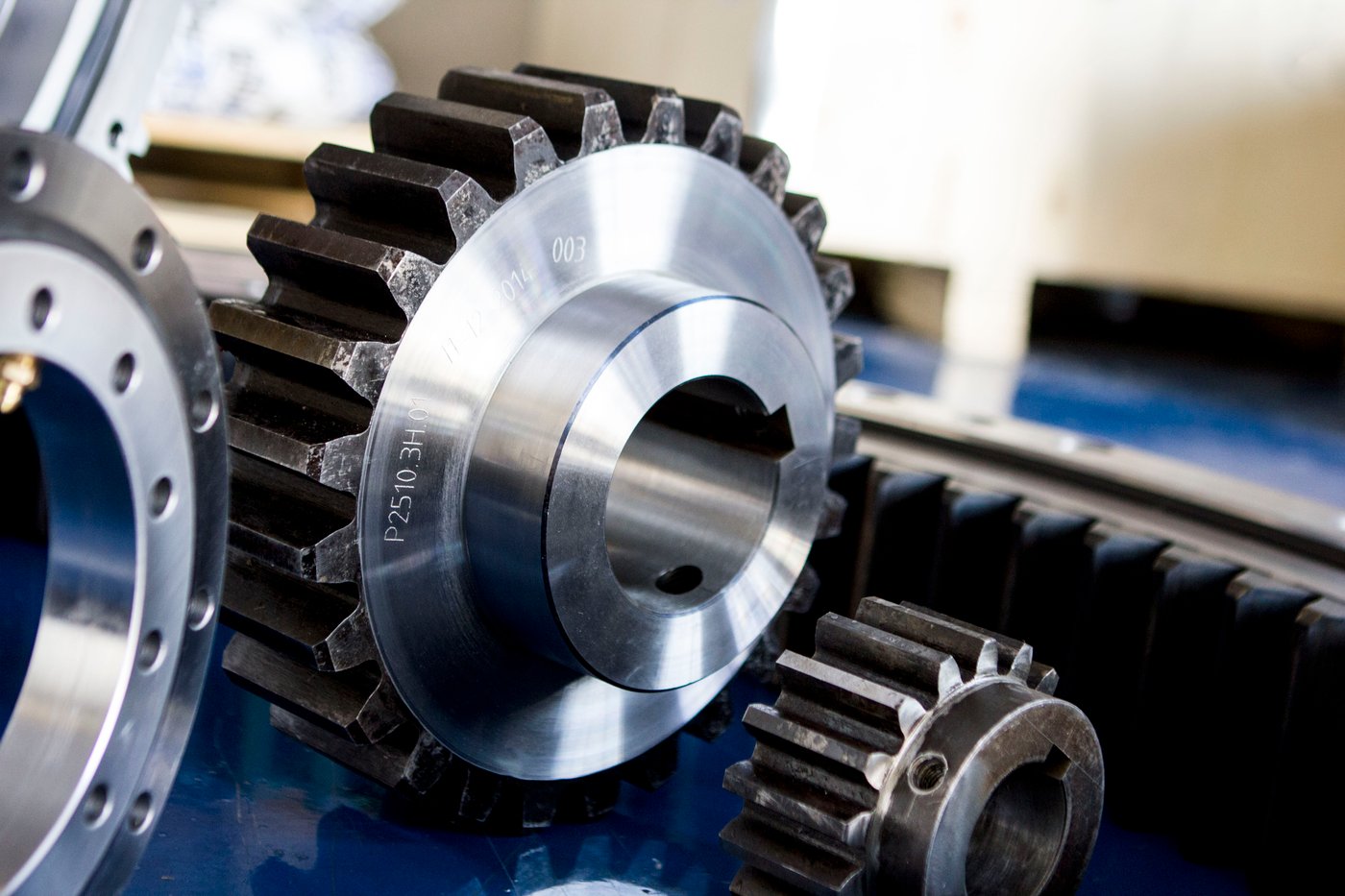
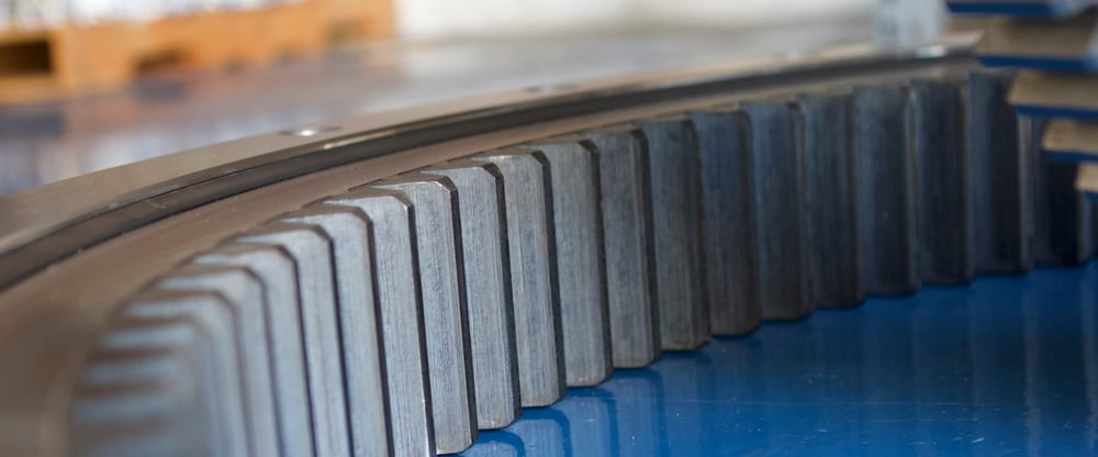
SlewPro’s 50 Series is a single-row cross roller slewing ring built on this geometry: a rectangular cross-section for high stiffness, induction-hardened raceways, and raceway diameters from 10 to 180 inches, with dynamic capacity up to 4,600,000 lb thrust, 2,200,000 lb radial, and 16,000,000 ft-lb of moment — available plain, internally geared, or externally geared, with matching pinions.
Where Cross Roller Slewing Rings Fit
The configuration’s combined-load capacity and rigidity map onto a specific set of industrial applications.
Material Handling and Cranes
Tower, mobile, and offshore cranes use a slewing ring as the primary rotation joint between the upper structure and the base. It carries the boom-and-load weight (thrust), the horizontal reactions (radial), and a large overturning moment that grows with load and radius — often with impact and swing. Cross roller geometry supplies the moment capacity, rigidity, and shock tolerance this duty demands; offshore service adds corrosion and wave loading, making sealing and raceway hardness part of the specification.
Solar Tracking and Renewable Energy
Utility-scale solar trackers rotate long rows of panels to follow the sun, and the slewing bearing must hold the torque tube against wind loads that impose large moments on a structure with significant offset mass. Rigidity and low backlash keep panels on the tracking target and limit wind-driven oscillation, while load capacity keeps the drive reliable over decades of daily cycling outdoors.
Radar, Antenna, and Tracking Pedestals
Radar pedestals, satellite-communication positioners, and tracking mounts need angular position to hold under wind and outdoor exposure. Wind on a large antenna creates a variable overturning moment; the ring must be stiff enough that deflection stays within the pointing budget. Cross roller geometry provides that rigidity along with the diameter and moment capacity these structures need, and outdoor service makes sealing, lubrication, and corrosion protection central to the specification.
What to Specify
A diameter and a single load number are not enough to select a slewing ring well. Four parameters decide whether the ring delivers its capacity and service life.
The full load case
Specify thrust, radial, and moment together, with their combinations through the duty cycle, and separate static (worst-case) from dynamic (operating) loads. Moment usually governs, so capture the load and its radius or offset explicitly.
Rigidity, not just load rating
Where deflection matters — antenna pointing, tracker alignment, crane tip control — ask for tilting stiffness and confirm that deflection under worst-case load stays within budget. SlewPro provides deflection analysis, including FEA, for the specific load case.
Gear and mounting
Choose plain, internal, or external gear for the drive layout, and confirm the bolt pattern, register diameters, and mounting-face flatness. Mounting-structure stiffness affects real-world load distribution, so it belongs in the conversation; matching pinions are available for the geared rings.
Environment: hardness, sealing, and lubrication
Confirm raceway hardness for the load, and specify sealing, corrosion protection, operating temperature range, and regreasing suited to the environment — offshore, coastal, desert, and arctic service each make different demands. For slow, heavily loaded rotation, specify EP and AW lubricant additives.
Conclusion
Cross roller slewing rings are not a better general-purpose bearing — they are specified because heavy industrial rotation demands combined thrust, radial, and moment capacity, high rigidity, shock tolerance, and a compact cross-section in one ring, and a single-row ball slewing ring cannot match that as efficiently. The alternating 90° rollers and their line contact are why the ring holds a crane jib, a solar tracker, or an antenna pedestal where it is put, cycle after cycle.
SlewPro’s cross roller slewing rings — led by the 50 Series across a 10-to-180-inch diameter range — are backed by application engineering that goes beyond catalog ratings, from load-case and deflection analysis to gear, mounting, sealing, and lubrication. Contact SlewPro or request a quote to start a specification grounded in the loads your application actually sees.